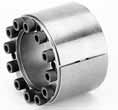
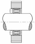
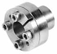
| Photo and diagram |  450 serie |
 | ||||
| Principal | The locking together of two
components is achieved by tightening one conical ring against
another. The outer ring will have the tendency to enlarge, and start
to press against the housing wall, whilst the inner will start to
force itself against the shaft. | |||||
| Mounting | Carefully clean the elements
involved, and apply a light film of oil to the surfaces which will
be in contact. Fit the assembly into the space in the hub, then
insert the shaft through the centre. Gradually tighten the screws
and uniformly increase the torque until the Torque level Ta, shown
in the tables, is achieved. The figures for T and Fax in these
tables are calculated assuming the assembly is done in this way ?
using oil. | |||||
| Attention | N use Molybdenum
disulphide (MoS2) based oils or greases, they will cause
considerable reductions in the friction torque. | |||||
| Disassembly | Remove the screws and
re-insert them in the extraction holes, increasing the torque
gradually once more until the cones separate. In case of re-use
after removal, re-oil the screws and threads once
more. | |||||
| Tolerance : Surface quality | A reasonably good machine
tool finish is sufficient.. Minimum surface quality of Rt max 16Ám Maximum admissible tolerances : Shaft h8, bore H8 | |||||
| Photos |  100 serie |
 250 serie | ||||
| Mounting in series |
| |||||