Methods of fixing to a shaft
| Attachment with a fixing screw | Attachment with a Key and Circlip | ||
 |
  | ||
| Attachment with a Cotter pin | Attachment with a Locking assy. | ||
 |
 | ||
| Attachment with a Locking ring | Attachment with a Self-lubricating bush | ||
  |
 |
| PRINCIPALS
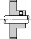
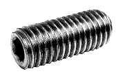
Assembly with a fixing |
  |
 |
ADVANTAGES
This type of fixing improves adherance |
| PRINCIPAL
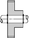
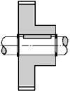
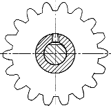
The use of a key attaches the gear to the shaft by stopping rotation between the two. A groove, or keyway must be machined into the bore and shaft. For manufacturing practicalities, the groove cut into the bore must traverse the whole width of the gear. | |
| A parallel key - is a rectangular piece of metal, embedded half and half into the shaft and hub. The machining of the groove in the shaft is done with the aid of a two bladed cutting tool. A keyway of this type is excellent for the transmission of high torque levels.
|  |
| Disk (or half moon) keys are used for the transmission of weaker couples. The machining of the keyway into the shaft is very easily done using a three bladed cutter. | |
 |
A keyway does not stop axial movement of the system. Therefore it must be combined with another locking system, such as a thread and bolt, or more simply, by circlips. |
| PRINCIPAL
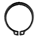
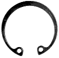
Circlips, stop axial movement between two componants.
UTILISATION The utilisation of these elements needs a groove to be cut into either the bore or the shaft. They are then fitted axialy, from one end of the shaft or bore with the aid of a specialised tool. Attention, a minimum (or maximum) clearance diameter is needed for the installation. | ||||
| ||||
| The use of these componants is often associated with a KEYWAY in the assembly of pulleys or spur gears. | ||||
| PRINCIPAL
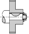
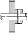
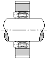
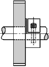
The cotter pin has the effect of immobilising one componant with respect to another, of assuring an accurate relative positioning of the two pieces, or of transmitting a movement. It can also play a safety role by shearing away in the event of a violent surcharge. UTILISATION Essentially, the pin is subject to shearing, and should therefore be used in cases where there is relatively little torque involved. It's usage is not recommended where frequent removal is necessary. The piercing of the pinholes is generally done after assembling the componants in order to assure perfect alignment.
| |||
 The
use of a cylindrical cotter pin needs the
precise machining of a hole through the shaft and gear. A rough
hole is good enough because the pins will adjust by deforming in
their seating. The
use of a cylindrical cotter pin needs the
precise machining of a hole through the shaft and gear. A rough
hole is good enough because the pins will adjust by deforming in
their seating.This property gives them a very good resistance to vibration. This type of assembly is excellent for small toothed wheels or pulleys, or gears with low modules. | |||
| PRINCIPAL
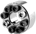
By tightening the screws, the user deforms a conical ring, and causes a strong force between the shaft and bore. The liasion obtained is complete and rigid (i.e. backlash free) , and easily removed. | |
 -> ->  | |
| ADVANTAGES
By
avoiding the manufacturing accidents which can be caused whilst
cutting keyways etc?This system actually increases the sectional
strength of the shaft and decreases both the concentration of stress
points and the phenomenon of metal fatigue cracking. |
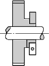
| Attachment by locking ring is a fast and efficient method of attaching all types of toothed wheels. Two solutions exist, locking with half a locking ring (type CT), or locking with the aid of a full collar (CC). | |||||
THE USE
OF A HALF-ROUND RING (CT)
| |||||
USING A
LOCKING RING (CC)
In both cases, the result is a completely rigid joint, which is perfectly suited to the transmission of high levels of torque. | |||||
| PRINCIPAL
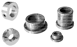
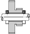
This very simple system provides a reliable, simple and
efficient rotational guidance. It manages to limit friction between
the shaft and bore with the aid of two self lubricating bushes (type
QAF or QAG), and at the same time, stopping axial movement of the
rotating object. | |||||
| |||||
| The use of self-lubricating Ollite QAG or QFM bushes imposes a maximum tolerance of f7 on the shaft and H8 on the bore (see ISO 2795 and 2796). | |||||
